Temporary prototype to permanent prototype!
- Initial design
- Shopping!
- Temporary prototype to permanent prototype!
- Finishing the Power Supply
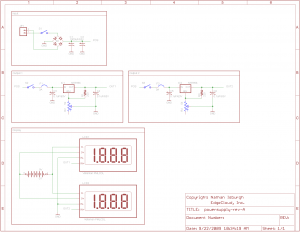
Now that I had a working system, I needed to make it a little more permanent. First of all, I wanted dual outputs, so here’s the new schematic I put together.
You’ll notice that the voltmeters are run off a separate battery. This frustrated me to no end. Basically, most digital voltmeters *require* an isolated power supply. You can get high end units that self isolate, but they’re about $100 each. I wanted digital for accuracy ( this problem only affects digital VM’s – analog would have worked as is ), so I just decided to go with the battery option and see how long it lasts. I’d be curious what it might have taken to separate off a 9V supply and isolate it from the variable outputs.. I messed with it for a while, but the closest I got was a voltmeter with a pretty heavy bow in it’s accuracy curve. ![]()
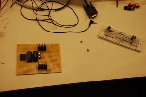
Anyhow, off to Radio Shack and Fry’s for a few more pieces! Proto board, plastic enclosure and extra parts to build a dual output power supply. After I cut the board down and drilled mounting holes, I started moving components from the breadboard to the more permanent proto board. Here’s a shot shortly after starting to solder. I mostly used the long leads from the components to bridge everything together. It’s not the prettiest option, but the cost/speed beats a one-off custom PCB. Note the beefy heatsinks for the regulators. An absolute must! I was reading 145 °F on the heatsink just powering a stamp, LCD and PING))) sensor.
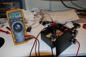
After a couple hours of soldering, fabrication and connecting parts, I had the beginnings of a working lab supply!
Up next, switches, voltmeters and binding posts!


