Wireless is GO!
I got my wireless link online several weeks ago and am just now posting. Lame, I know, but after it was up I immediately set about working it towards something useful. I’ll save that for another post; right now I want to detail what was involved in getting the RF link up.
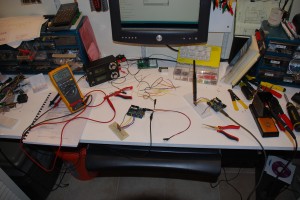
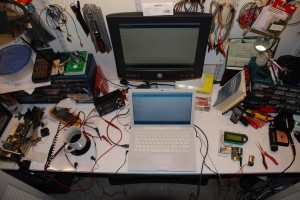
First off, the hardware: two arduinos and two Nordic radios. I used the Arduino USB boards, one RP-SMA board and one chip antenna board. Why two different RF configurations? To test range, sensitivity and see what they look like. Anyhow, the Nordic chips on these boards ( nRF24L01+ ) interface via the Serial Peripheral Interface bus standard, or SPI for short. SPI is a fairly simple protocol, but the timings can get tricky. Fortunately, the Arduino has an SPI interface built in, so all we need to do is download and install the SPI library from the Arduino Playground. Better still, someone sat down and wrote a small interface library for the Nordic chips which encompasses a subset ( the important ones ) of the command set! Find details and download Mirf.zip here. Update: I updated and fixed some things with the Mirf library and have released it on the site. Check out the “Software” tab at the top, or go here.
Now that you have the necessary software, you need to hook up the hardware. The bare minimum to get the radios talking is described at the top of the example files from Mirf.zip. Just open the ping_client and ping_server example files to get started. Connect Vcc and Ground to your radio, as well as the 5 pins listed at the top of the example files: MISO, MOSI, SCK, CE and CSN. Set up both Arduinos, and install the client code on one, the server code on the other. Use a wall wart to power one while you watch console on the other. You’ll see the round trip times displayed on the client, and packet messages on the server!
One thing I immediately noticed in testing was that the client code would hang if the connection dropped a packet. That made testing range rather cumbersome, so I looked at the code in ping_client and found this:
while (!Mirf.dataReady()) {
  //Serial.println("Waiting");
}
Hrmm, if he didn’t get the packet back from the server, he’d hang forever, since the server only replies once. Let’s put a timeout in here:
unsigned long time = millis();
while(!Mirf.dataReady()){
  if ( ( millis() - time ) > 3000 ) {
    Serial.println( "Timeout!" );
    break;
  }
  //Serial.println("Waiting");
}Simple! Three second timeout. Now we can do some range tests, and when the connection drops, it will automatically attempt to reestablish after the timeout. You can barely see on the monitor console messages regarding their communication! Perfect!
Well, not quite. I don’t really want to walk around the house with a laptop, arduino, breadboard, nRF module and wires all over the place just to see the output on the console! Let’s interface a serial LCD so we can see real time RTT’s right on the LCD.
/**
 * Example code to run RTT tests between nRF modules and display results on serial LCD
 *
 * Pins:
 * Hardware SPI:
 * MISO -> 12
 * MOSI -> 11
 * SCK -> 13
 *
 * Configurable:
 * CE -> 8
 * CSN -> 7
 *
 * LCD Serial In -> 2
 */

#include
#include
#include
#include
#include
#include

// Scott Edwards BPP serial lcd backpack on pin 2
LCDSerialBackpack lcd( 2, SE_BPP, 9600 );

void setup(){
  Serial.begin(9600);
  lcd.begin();
  lcd.clear();
  lcd.home();
  lcd.blOn();
  lcd.print("Starting wireless");
  /*
   * Setup pins / SPI.
   */

  /* To change CE / CSN Pins:
   *
   * Mirf.csnPin = 9;
   * Mirf.cePin = 7;
   */

  Mirf.init();

  /*
   * Configure reciving address.
   */

  Mirf.setRADDR((byte *)"clie1");

  /*
   * Set the payload length to sizeof(unsigned long) the
   * return type of millis().
   *
   * NB: payload on client and server must be the same.
   */

  Mirf.payload = sizeof(unsigned long);

  /*
   * Write channel and payload config then power up reciver.
   */

  /*
   * To change channel:
   *
   * Mirf.channel = 10;
   *
   * NB: Make sure channel is legal in your area.
   */

  Mirf.config();

  Serial.println("Beginning ... ");
  lcd.cursorTo( 2, 0 );
  lcd.print( "Done" );
  delay(500);
  lcd.clear();
  lcd.home();
  lcd.print( "RTT: " );
}

void loop(){
  lcd.cursorTo( 1, 5 );
  unsigned long time = millis();
  unsigned long time2;
  byte fail = 0;

  Mirf.setTADDR((byte *)"serv1");

  Mirf.send((byte *)&time);

  while(Mirf.isSending()){
  }
  delay(10);
  while(!Mirf.dataReady()){
    if ( ( millis() - time ) > 3000 ) {
      lcd.print( "Timeout!        " );
      fail = 1;
      break;
    }
    //Serial.println("Waiting");
  }

  if ( !fail ) {
    Mirf.getData((byte *) &time);
    time2 = millis();

    Serial.print("Ping: ");
    Serial.println(time2 - time);
    lcd.print(time2 - time);
    lcd.print( " ms        " );
  }

  delay(1000);
} Here we go. Output to LCD, status messages and we’re mobile with a 9 volt battery! What’s this LCDSerialBackpack.h though? Well, I use serial LCD’s a lot, and so I’m putting together a library to simplify their interface into a standard Print interface with special commands like clear() and blOn(). Makes the code easier to write, and I don’t have to remember the command sequences every time I need an LCD. After I clean the library up some more, I’ll put it up here for anyone that’s interested. If you’re following along at home, just rip out the lcd.* statements and put in the necessary code to display to your LCD.
Anyhow, simple to put together wireless connection. I’m very pleased. Like I said, I immediately set about making this thing useful ( RTT’s are nice and all, but let’s start pushing some real data over the airwaves! ), so expect future posts with more meat!


Hi, here it goes: it’s not my filed (I’m specialized of Inudustrial engineering) and I have project on my treineeship now in Spain related to electronics: wireless transfer of data from one board to doughter board usning nRF24L01 and with ATmega 328P.. problem arises when i try to programm in C -> i don’t know where to start! if you could help me with some kind of simple code in C that e.g. turns LED on the other board? My task is actualy to transform noise measurements collected with microphone to onother board that is connected to PC who collects data during the day.. please
 Mozart’s bday
  ?!
?!
I’m Ana from Croatia; desperately need help
btw. if you have doubt help me or not will it be useful to mention that we are born on same day
please if you could help me and send me any helpful advise or suggestion on my email
Hi Ana! I’ll be happy to try and help you out! It sounds like a neat project. Email sent!
Cheers
Hey Chris,
Got any updates on the MIRF library? I am planning to give your library a go but have not seen any updates lately (I check your website regularly). Cheers
JR,
I’m sorry I haven’t been updating the website recently.. Changed jobs, started a company – things are hectic! But the code has worked well for me – my wireless mesh network using the code has been running solidly. Please try out the code and let me know!
Cheers,
Nathan
Hello,
I just downloaded the MIRF version you have on this site and loaded the ping_server unchanged into my arduino.
When i run it ( There is no client connected ) and open the serial monitor, i see endless stream of “got packet” and sent reply messages. In other words, Mirf.dataReady() is always true even though i have no transmitter active!
Any ideas? BTW, the same thing happens with the playground version.
Thanks for dropping a comment. I like knowing that at least a few people are seeing this site!
That is very strange behavior.. I have not seen that particular issue before. Are you sure you have the radio hooked up correctly, each pin connected exactly as it says in the example code? Let me know what you find..
Cheers,
Nathan