Power Supply

Finishing the Power Supply

Posted in Electronics, Power Supply on October 25th, 2009 by nisburgh – Be the first to comment
This is part 4 of 4 in the series Variable Power Supply

I now had a power supply that delivered two independent, variable outputs – but I had no easy way to hook up to the outputs, know their voltages or switch them ( without unplugging the cord ). So, to round out the final product, I added some 3 amp breakers, voltmeters, switches and binding posts.

Drilling complete

Drilling complete

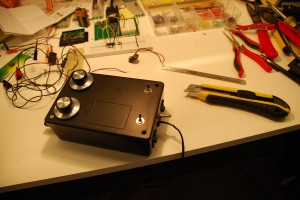
Here’s a shot of the project box after drilling holes for four binding posts, main power switch, power input cord and the breakers.

Connected together - lots of wires!

Connected together - lots of wires!

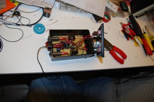
In this shot, you can see that I’ve installed the breakers ( long black devices on the left side ), the main power switch ( red switch on left ), the power input cord feeds into the blue screw-down terminal block and the individual control switches on the lid which allow you to control each output. A whole mess of wires, but not unmanageable. BTW, I found some great strain relief grommets at Fry’s. Just drill a hole in your box, put your wire in the strain relief grommet, snap the top in place and shove it into the hole – it provides a very secure and robust wire connection that prevents putting any strain on the screw-down terminal on the PCB. Definitely keep an eye out for those.

Binding posts!

Binding posts!

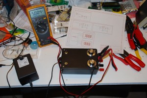
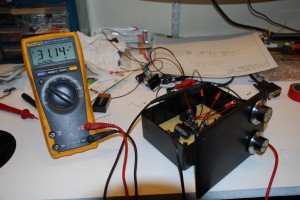
Binding posts installed, cover secured – and pumping out a near perfect 5 volts! The last step is to add the voltmeters.

Cutting in some windows

Cutting in some windows

Cutting out the holes for the digital panel meters. The meters I found were Velleman units from Fry’s. Easy to use and install, but not isolated like I mentioned before. Follow the instructions included with the unit to move the decimal point jumper ( blob-o-solder ). Most digital panel meters are shipped from the factory ready to read 0-200mV. That’s not too useful for our application, so we need to follow the instructions to create a voltage divider on the input so we can display in the range of 0-20VDC. It’s actually quite simple – you remove a couple of 0402 SMT resistors, then solder in some new ones ( SMT or PTH – connections are provided for both ) – a 10M and a 100k for the 0-20VDC range, if I recall correctly. After that, hook up a battery and the sensor leads. Use your calibrated multimeter to dial in 10 VDC on your power supply, then adjust the trimpot on the back of the panel meter until it reads 10.00 VDC. Now your new panel meter is calibrated and all that’s left is mounting it in the project box!

Finally!  My own dual-output variable power supply!

Finally! My own dual-output variable power supply!

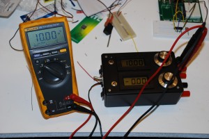
Final product! You’ll notice that the main power switch changed – I had to do this so I could switch the power to the supply and the voltmeters with one switch ( DPST ). That wraps up the series on building a dual output variable power supply for the home workbench. Feel free to leave questions or suggestions in the comments!
Temporary prototype to permanent prototype!

Posted in Power Supply on October 12th, 2009 by nisburgh – Be the first to comment
This is part 3 of 4 in the series Variable Power Supply

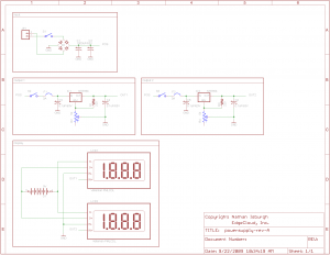
Now that I had a working system, I needed to make it a little more permanent.  First of all, I wanted dual outputs, so here’s the new schematic I put together.

Simple variable power supply schematic

Simple variable power supply schematic

You’ll notice that the voltmeters are run off a separate battery.  This frustrated me to no end.  Basically, most digital voltmeters *require* an isolated power supply.  You can get high end units that self isolate, but they’re about $100 each.  I wanted digital for accuracy ( this problem only affects digital VM’s – analog would have worked as is ), so I just decided to go with the battery option and see how long it lasts.  I’d be curious what it might have taken to separate off a 9V supply and isolate it from the variable outputs.. I messed with it for a while, but the closest I got was a voltmeter with a pretty heavy bow in it’s accuracy curve. :)


Coming along nicely

Coming along nicely

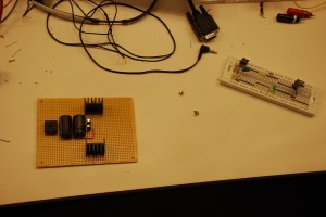
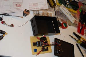
Anyhow, off to Radio Shack and Fry’s for a few more pieces!  Proto board, plastic enclosure and extra parts to build a dual output power supply.  After I cut the board down and drilled mounting holes, I started moving components from the breadboard to the more permanent proto board.  Here’s a shot shortly after starting to solder.  I mostly used the long leads from the components to bridge everything together.  It’s not the prettiest option, but the cost/speed beats a one-off custom PCB.  Note the beefy heatsinks for the regulators.  An absolute must!  I was reading 145 °F on the heatsink just powering a stamp, LCD and PING))) sensor.


Not easy to use, but it works!

Not easy to use, but it works!

After a couple hours of soldering, fabrication and connecting parts, I had the beginnings of a working lab supply!


Up next, switches, voltmeters and binding posts!

Shopping!

Posted in Power Supply on September 24th, 2009 by nisburgh – Be the first to comment
This is part 2 of 4 in the series Variable Power Supply

Now that I had a basic design to prototype, I needed to collect all of the parts to test out the basic power supply circuit.

First iteration - variable power supply

First iteration - variable power supply

Austin does not have many options when it comes to electronics parts stores.  Up north you have Frys Electronics.  They have a pretty decent selection of components ( mostly NTE ), project boxes, wire, switches, supplies, tools and what not.  I’m not sure how long they will continue stocking this gear, though, as their real bread and butter seems to be consumer electronics – computers, stereos, tv’s, etc.  None the less, I found most of what I needed to complete a simple breadboard test of the supply.  Here’s a short list of what I used to put everything together.  The prices are from memory, so the accuracy is sure to be lacking.  :)

  • NTE 956 – $2 – adjustable positive voltage regulator, 1.5A, 1.2-37 VDC
  • NTE 5312 – $4 – 8A single phase bridge rectifier, up to 70VAC input
  • 1000 μF electrolytic capacitor, 50VDC – $4.  ( Always remember to derate your caps.  50% is the rule of thumb, so technically I shouldn’t run this power supply over 25V.  If you want to run all the way up to 37V, get 75V or better caps. )
  • 0.1 μF electrolytic capacitor, 50VDC – $0.50
  • 1 μF electrolytic capacitor, 50VDC- $0.50
  • 10 turn, 5k Ω potentiometer – $12 ( This was a high quality, audio grade pot ).  I went with the 10 turn for precision voltage selection.  Any 5k pot will work, just remember that the shorter the wiper travel, the harder it will be to set your voltage to exactly what you need.
  • A knob to fit the pot – $2

I had a breadboard and all the resistors I could ever want in the lab at home, so I didn’t need to buy them.  I probably also could have avoided buying the smaller caps, but I wanted to make sure I had the exact sizes.

With loot on hand, I carefully put the circuit down and double-checked every connection.  You might be wondering about some of the other parts listed in the schematic that I didn’t buy.  Since I was just testing at this point, I didn’t invest in a switch or a fuse, figuring that I would simply connect or disconnect a fused power source to verify the design.

Speaking of power sources, I looked for a decent transformer but couldn’t find one that would give me the voltage/amperage combination I sought.  Optimally, a transformer wound for a 120 VAC primary with a 36 VAC secondary rated for at least 60 VA ( or watts ) would allow me to run the circuit at full capacity – up to the maximum voltage and amperage the regulator can handle.  Check out an online giant like Mouser to find the perfect transformer for the job.

Since I couldn’t find one that matched those specs, I dug through my wall wart collection and found an old printer supply that output 28 VDC and could push 1A.  VDC?!  The schematic calls for a VAC input!  No big deal.  You can connect VDC or VAC to a bridge rectifier and it will correctly provide the positive and negative potentials at it’s outputs regardless of how you hook up the input.  Just check the schematic if you don’t believe me.  :)   Having the rectifier in place gives my power supply the ability to handle direct or alternating current input.

With everything checked on the breadboard, I hooked up the wall wart and did the first smoke test.  Nothing smoked, popped or fried!  Good sign!  Hooking my Fluke to the output, I verified a roughly 1.2VDC signal on the output.  Dialing up the pot, I watched the voltage climb up and up, eventually topping out at about 30 VDC.  Success!

Next up, conversion to dual variable output, dissipation consideration and the beginning plans for a permanent power supply system.

Initial design

Posted in Power Supply, Schematics on September 22nd, 2009 by nisburgh – 2 Comments
This is part 1 of 4 in the series Variable Power Supply

I started tinkering with electronics again recently and quickly realized the need for a good power supply.  Shopping around, it became apparent that a decent dual-output unit was going to set me back quite a bit.  So I started doing some research on what would be involved in a simple little power supply I could build on my own.  Enter the LM317 variable positive voltage regulator.  Fantastic little IC capable of providing up to 1.5A and 1.2-36 volts.

First iteration - variable power supply

First iteration - variable power supply

Here was the first schematic I put together from various circuit designs available around the internet.

Working from left to right, we have our 120VAC input, which goes through a switch and a fuse to energize a basic 120/28 or 120/36 step down transformer.  ( BTW, it’s very difficult to find a transformer of that size with the VA rating to handle a couple of these power supply circuits at full output! ).

Now that we’ve stepped down our common household voltage, we rectify it using a standard bridge rectifier B1 ( 2A for safety ), followed by a large capacitor and a small one.  The 1000μF cap is there to provide substantial current in the event of transient demand spikes.  This large capacitor, though, does not respond very quickly, so we paired him up with a 0.1μF cap for higher frequency pulse suppression.  These caps help cut down on voltage ripple in the eventual output.

Next we have the workhorse of the circuit, the LM317.  Note that most manufacturers that produce regulators will have something comparable to the 317.  You don’t have to have the actual National Semiconductor part for this project ( I don’t!  I use an NTE956 because it was readily available at Fry’s Electronics ).  Any 1.2V-36V variable positive voltage regulator with a 1.5A output will do fine.  Double check that pinout!

Anyhow, the 220Ω resistor ties back in to the adjust pin as feedback gain, which you then pull down with the 5kΩ potentiometer.  The more current fed into adjust, the higher the output voltage.  Hence, as you increase resistance on the pot, you increase the output voltage!  All the way up to about 36VDC!  BTW, another fantastic feature about these regulators is that they’re extremely hardy, with built-in overload and thermal protection features.

Finishing up the circuit walkthrough, we have one more cap, C4, rated at 0.1μF, for further noise suppression and to hopefully limit our voltage ripple to an acceptable level.  Once I get a good oscilloscope, I’ll let you know what the actual ripple is.

In later posts, I’ll cover the ongoing construction of this project, along with adding a second output and voltmeter displays.