LED Fun
Posted in Projects on September 26th, 2009 by nisburgh – 2 CommentsI decided to swing by RadioShack after work yesterday and see what kinds of fun components I could snag. I came across this tri-color LED ( datasheet – FYI: the green and blue pins are accidentally swapped in the data sheet ) from RadioShack for $2.99. I’ve been looking at the same thing over on SparkFun – I just hadn’t gotten around to placing an order yet. What follows is the simple circuit and software I wrote to give this cool LED a test run. I used a Basic Stamp 2 module, 3 resistors and the LED.
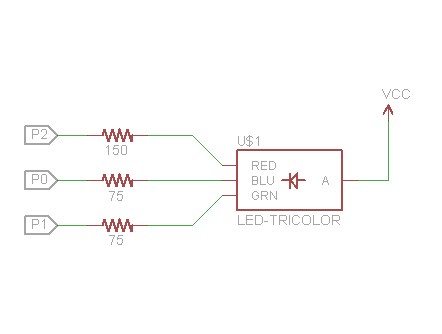
First of all, this is how you hook up the circuit. Those resistance values are calculated using the typical voltages on the data sheet. I limited the amperage to 20 mA to protect the Stamp module and prolong the LED life. I didn’t have 75Ω on hand, so I substituted 82Ω.
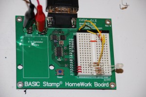
Here’s a picture of the HomeWork Board I used to wire up the circuit. Ignore those wires at the top of the breadboard – that was for another project. ![]()
I’ve uploaded the ( ugly ) source code I threw together to make the LED run through various sequences. Here is a small snippet showing a good way to achieve a smooth, randomly varying color sequence. I think this is a great way to show off an RGB LED:
rand = 188
r = 200
g = 200
b = 200
dr = 2
dg = 2
db = 2
DO
  PWM Red, r, 1
  PWM Green, g, 1
  PWM Blue, b, 1
  IF rand > 10 THEN
    RANDOM rand
    IF rand < 85 THEN
      dr = -dr
    ELSEIF rand < 170 THEN
      dg = -dg
    ELSE
      db = -db
    ENDIF
  ENDIF
  r = r + dr
  g = g + dg
  b = b + db
  IF r = 2 OR r = 254 THEN
    dr = -dr
    r = r + dr
  ENDIF
  IF g = 2 OR g = 254 THEN
    dg = -dg
    g = g + dg
  ENDIF
  IF b = 2 OR b = 254 THEN
    db = -db
    b = b + db
  ENDIF
LOOP
All of the variables are declared as bytes, and the Red, Green and Blue names are PIN aliases. The Stamp is a relatively slow processor, running at about 4000 PBASIC instructions per second. Such a slow execution speed forced me to get a little creative with the code to get a visually smooth shifting of colors. A quick run-down of the code:
- Use PWM to output a very short ( 1ms ) burst of analog voltage according to the corresponding variable for each color. The astute will note that it's actually more of an "input" of voltage, as the current actually flows from Vcc through the LED and into the Stamp. Remember this when calculating current draw, as the Stamp can only sink 25mA per pin, and 50mA total per IO pin bank.
- Decide randomly whether you're going to adjust one of the delta factors. This helps minimize the number of times you're doing extra comparisons and math. We have to keep those operations to a minimum because the LED is not lit during that time, and the longer you take to relight the LED, the more flicker you'll see.
- If you are adjusting a delta, just randomly pick one to flip.
- Add the deltas to the values
- If one of the values gets too low or too high, flip the delta and re-add so you don't roll around, because the Bytes will roll over from 0 to 255 and 255 to 0. If you let that happen, the particular color it affects will suddenly turn on or off.
Feel free to tweak some of the numbers. You can achieve some neat effects by stretching out the output times, playing with which colors vary when, or even expanding the code to vary more than one delta at a time.
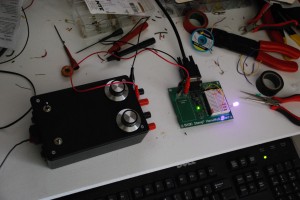
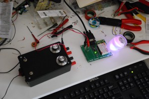
Here are a couple of action shots for your amusement. Enjoy!


