So one of the first sensors I would like to implement for the sensor mesh is a simple water detector. You know, for washer machines, refrigerators, water heaters, etc. Let’s you know when you’ve got a leak. I wanted the circuit to be simple and low power, since it would almost certainly be run off a battery, and the RF gear alone was going to suck most of the available juice. I also wanted a circuit external to the microcontroller to remember ( latch! ) if we had a leak condition, that way I could let the microcontroller and RF module sleep for a few minutes between checks, but still capture transient leak conditions ( What if a droplet hit the sensor, but then rolled off due to slope? ).
Anyhow, water is not nearly as conductive as you would think. Rudimentary testing of water droplets indicated about 200k-500k of resistance. My first, simple attempt at a water detection circuit did not take this into consideration.
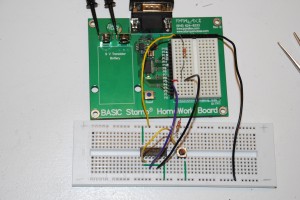
Simplistic water detection circuit
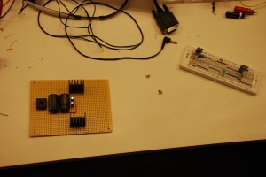
Here’s a snapshot of the test circuit I built. It works great using that little tactile switch. But it doesn’t have the capability to pull the S input on the S-R flip flop to ground when running through water. That’s simply because the path to ground for the VCC pullup has too high a resistance ( 200k-500k through water ) to drop the voltage below 0.8V, necessary for a TTL low signal. I didn’t bother putting together an eagle schematic for this design since it didn’t work.   The astute will notice I don’t actually have it wired up to an R-S flip flop ( 74279 ). I didn’t have one on hand, so I built one with a 7400 I had in stock.
At his point, I figured that I needed some amplification of the current I was able to push through a drop of water, so obviously a transistor came to mind. A standard NPN transistor ( 2N2222 ) wouldn’t do, though, since it doesn’t provide adequate amplification of the base current produced by 5V pushing across 200k-500k resistance. What I needed was a Darlington transistor! Amplify the amplification!
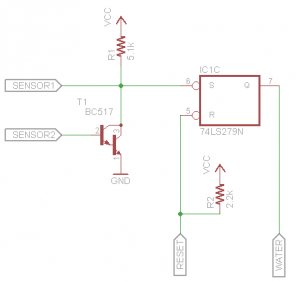
Working water detector!
Here’s the circuit I put together using a Darlington NPN transitor to amplify the current that could be pushed through a drop of water at 5VDC. When the power turns on, the microcontroller needs to reset the S-R flip flop by cycling the Reset line low then hold it high. We have the S-R flip flop to “remember” when we have a moisture condition for the sleeping microcontroller. The S input has a pullup resistor R1 just because it’s bad practice to leave a TTL input floating. We connect that same signal to one end of our sensor probe ( SENSOR1 ), as well as the collector on our Darlington, T1. The other side of our sensor ( SENSOR2) connects to the base of T1. If we can push a mere fraction ( think millionths ) of an amp through that sensor, the Darlington is going to open up and dump all of the collector current through it’s emitter into ground. This will draw the S input to ground, flipping the water signal on. The water signal will not turn off until the Reset line ( R on the S-R flip flop ) is pulled low by the microcontroller. Speaking of which, R2 is a pullup to make sure we don’t accidentally reset the flip flop during sleep/wake-up cycles, because on some microcontrollers, like the Stamp used here, the pins switch to inputs for 18 ms until the interpreter takes control.
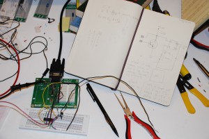
Working water detector prototype!
I put this design together and tested it – it couldn’t work better!  In fact, it’s able to detect the microamps that were able to push through my *body*. The Hfe on the BC517 Darlington is 30k. *Serious amplification!* Now I had a simple circuit that could remember a closed condition ( leak ) and could detect current flowing through megaohms ( necessary for detecting the presence of water ). Mission accomplished.
Messy, but functional!
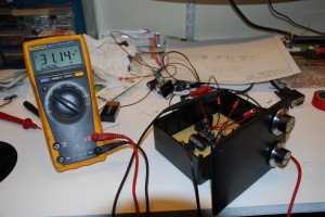
Here’s a final shot of my work area. Prototype, circuit, Jack Daniels, power supply, mess and all!

![]()
